STL format
- STL (stereolithography) is a file format native to the stereolithography cad model.
- It is widely used for rapid prototyping , 3 d printing and computer aided manufacturing.
- The main purpose of the stl file format is to encode the surface geometry of a 3d object.
- It encodes this information using a simple concept called tessellation.
- Tessellation is the process of tiling a surface with one or more geometric shapes such that there are no overlaps or gaps.
- Tessellation can involve simple geometric shapes or very complicated shapes.


ASCII stl file format
file start with mandatory line:
solid <name>
file ends with mandatory line :
endsolid <name>
the file stores information about the covering triangle.
Binary stl file format
- If the tessellation involves many small triangles , the ASCII stl file can become huge.
- This is why a more compact binary version exists.
Special rules for the stl format
- The stl specification has some special rules for tessellation and for storing information.
- The vertex rule : it states that each triangle must share two vertices with its neighboring triangles.

- The orientation rule : it says that the orientation of the facet must be specified in two ways.

- The traingle sorting rule : it recommends that the triangles appears in ascending z value order.
- The all positive octant rule : it says that the coordinates of the triangle vertices must all be positive.


Advantages of stl file format
- Provides a simple method of representing 3d cad data.
- A de facto standard has been used by most cad systems and RP systems.
- It can provide small and accurate files for data transfer for certain shapes.
Disadvantages of stl file format
- The stl file is many times larger than the original cad data file.
- The geometric flaws exist in the stl file.
- The subsequent slicing of large stl files can take many hours.


Additive manufacturing technologies
- Selective laser sintering (SLS) or direct metal laser sintering.(DMLS)
- Stereolithography (SLA)
- Fused deposition modelling (FDM)
- 3d printing
- Laminated object manufacturing (LOM)
- etc
SLS and DMLS
- A laser sinters each layer of metal powder so that the metal particles adhere to one another.
- DMLS machines produce high resolution objects with desirable surface features and required mechanical properties.
- Nearly 0.1 mm thick layers.
- The part building takes place inside an enclosed chamber filled with nitrogen gas to minimize oxidation and degradation of the powdered material.
- The powder in the building platform is maintained at an elevated temperature just below the melting point and/or glass transition temperature of the powdered material.
- Infrared heaters are used to maintain an elevated temperature around the part being formed.
- A focused co2 laser beam is moved on the bed in such a way that it thermally fuses the material to form the slice cross section.
- Surrounding powders remain loose and serve as support for subsequent layers.


3D printing:
- It is an indirect process in two steps.
- After applying a powder layer on the build platform , the powder is agglomerated tanks to a binder fed through the printer nozzle.
- The operation is repeated until parts are produced, which shall be then removed carefully from the powder bed , as they are in a green stage.
- The metal part solidification takes place in a second step , during a debinding and sintering operation , sometimes followed by an infiltration step.
- It is more productive then laser beam melting andd requires no support structure. Besides it provides a good surface quality by using one of several post processing techniques.


Stereolithography (SLA)
- It uses photopolymerisation to print ceramic objects. it is also called photopolymerization.
- The process employs a UV laser selectively focused into a vat of photopolymer resin.

- The uv curable resin produce torque resistant parts that can withstand extreme temperatures.
- The source supplies the energy that is needed to induce a chemical reaction , bonding large no. of Small molecules and forming a highly cross linked polymer.
- The uv light comes from a laser , which is controlled to scan across the surface accoding to the cross section of the part that corressponds to the layer.
- The laser penetrates into the resin for a short distance that corresponds to the layer thickness.
- The first layer is bonded to a platform. which is placed just below the surface of the resin container.
- The platform lowers by one layer thickness and the scanning is performed for the next layer.
- This process is continued until the part has been completed.

Facts about SLA
- Each layer is 0.076 mm to 0.05 mm thick
- Starting materials are liquid monomer
- Polymerization occurs on exposure to uv light produced by laser scanning beam.
- Scanning speed 0.5 to 2.5 m/s
Part build time in SLA
- Time to complete a single layer:
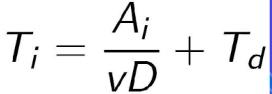

where Ti = time to complete layer i;
Ai = area of layer i;
v = average scanning speed of the laser beam at the surface
D = diameter of the spot size
Td = delay time between layers to reposition the worktable.
- Time to build a part ranges from one hour for small parts of simple geometry up to several dozen hours for complex parts.
- SLA build time cycle:


where Tc = STL build cycle time ; n1 = number of layers used to approximate the part
Fused deposition modelling (FDM)
- It uses a heating chamber to liquify polymer that is fed into the system as a filament.
- The filament is pushed into the chamber by a tractor wheel arrangement and it is pushing that generates the extrusion pressure.
- The major strength of it is in the range of materials and the effective mechanical properties of resulting parts made using this technology.
- Parts made using fdm are amongst the strongest for any polymer based additive manufacturing process.


Laminated object manufacturing and ultrasonic additive manufacturing
- LOM and uam are two sheets lamination method.
- LOM uses alternate layers of paper and adhesive , while uam employs thin metal sheets conjoined through ultrasonic welding.
- LOM excels at creating objects ideal for visual or aesthetic modeling.
- UAM is a relatively low temperature low energy process used with various metals , including titanium , stainless steel and aluminium .
Electron beam melting
- The ebm process utilizes a high power electron beam that generates the energy needed for high melting capacity and high productivity . The hot process allows you to produce parts with no residual stress and the vaccum ensures a clean and controlled environment.
Selective laser melting or direct metal laser melting or laser powder bed fuion
- Materials are fully melted in DMLM and EBM processes.
- With dmlm , a laser completely melts each layer of metal .
- Ideal for manufacturing dense , non porous objects.

- A powder layer is first applied on a building platform with a recoater and a laser beam selectively melts the layer of powder. Then the platform is lowered by 20 um to 100 um and a new powder layer is applied.
- The laser beam melting operation is repeated.
- After a few thousand cycles , the build part is removed from the powder bed.

Different additive manufacturing processes:
- Powder bed fusion
- Material extrusion
- Directed energy deposition
- Material jetting
- Binder jetting
- Sheet lamination
- Vat polymerization
Powder bed fusion
- This technology is used in a variety of AM processes , including direct metal laser sintering , selective laser sintering ,selective heat sintering , electron beam melting and direct metal laser melting.
- These systems use lasers , electron beams or thermal print heads to melt or partially melt ultra fine layers of material in a three dimensional space.
- As the process concludes , excess powder is blasted away from the object.
- Spooled polymers are extruded or drawn through a heated nozzle mounted on a movable arm.
- The nozzle moves horizontally while the bed moves vertically , allowing the melted material to be built layer after layer.
- Proper adhesion between layers occurs through precise temprature control or the use of chemical bonding agents.
- Material extrusion is one of the most well known additive manufacturing processes.


- An electron beam gun or laser mounted on a four or five axis arm melts either wire or filament feedstock or powder.
- DED is similar to material extrusion , although it can be used with a wider variety of materials , including polymers ,cermics and metals.
- With material jetting a print head moves back and forth , much like the head on a 2 D inkjet printer.
- However it typically moves on a x,y and z axis to create 3d objects.
- Layers harden as they cool or are cured by ultravoilet light.
- It is similar to material jetting , except that the print head lays down alternate layers of powdered material and a liquid binder.
- LOM and uam are two sheet lamination methods.
- LOM uses alternate layers of paper and adhesive while uam employs thin metals sheets conjoined through ultrasonic welding.
- LOM excels at creating objects ideal for visual or aesthatic modelling . Uam is a relatively low temp. low energy process used with various metals , including titanium , stainless steel and aluminium.
- An object is created in a vat of a liquid resin photopolymer.
- A process called photopolymerization, cures each microfine resin layer using uv light precisely directed by mirrors.
- Thermoplastic
- Metals
- Biochemicals
- Composites
- Ceramics
- Freedom to design and innovate without penalties.
- Rapid iteration through design permutations.
- Excellent for mass customisations.
- Elimination of tooling.
- Green manufacturing
- Minimal material wastage
- Energy efficient
- Enables personalised manufacturing
- Unexpecting pre and post processing requirements
- High process cost
- Lack of industry standards
- Low speed not suitable for mass production
- Inconsistent materials
- Limited number of materials
- High equipment cost for high end manufacture
- Porosity (0.99 % density achieved)
- Aerospace
- Medical
- Manufacturing
- Automotive
- Lifestyle
- Oil and gas
- Food and beverage
- Consumer electronic


, Mechanical engineering)
0 Comments