Basics of electromagnetic induction
- Whenever there is a change in the magnetic flux linked with the coil, an EMF is induced.

- If magnet is stationary then flux remain constant in the coil, there will not be any induction.
- If magnet is moving left side then flux will changes in the coil there will be induction.


Linear variable differential transformer
- It is a displacement sensor which is used to measure linear displacement, angular displacement.
- It works on the principle of electromagnetic induction (mutual inductance variation).
- It consists of single primary coil and two secondary coils which are connected in series opposition.
- It has movable magnetic core which couples the magnetic flux generated by primary coil to secondary coil.


Resolver
- Let us analyse the below diagram

- It is a position sensor which is able to measure linear displacement ,angular displacement.
- It works on electromagnetic induction.
- It has single primary coil which acts like rotor and two secondary coil which acts like stator.
- At each position of the primary winding the component of magnetic field is coupled with secondary windings. As a result we will get voltage at both the secondary windings.
- The ratio between the amplitude of output voltage across secondary winding provides the information shafts position.


Construction and working
- Inductosyn is a position sensor which is used to measure linear displacement ,angular displacement .
- It works on the principle of electromagnetic induction.
- It consists of two parts scale which is static and slider which is movable element .
- Scale :it has trace of conductive material which is regular rectangular shape as shown in figure.
- Slider box: it has two sliders and each slider is in regular rectangular shape as shown in figure.
- When the slider box displaces laterally on the scale then voltage will be generated across the slider because of induction .
- When the conductor of slider lies exactly above the conductor of scale then voltage generated across slider will be maximum.

- 23 conductor of scale are behaving like electromagnet.

Construction
- It consists of a rotor which rotates with rotating shaft and a coil which is winded on magnet.
- The rotor has teeth made up of magnetic material so it is called a toothed rotor.
- A transformer is used to collect the voltage from the coil.
- Electronic counter count number of pulses in second.
- Pulse frequency is used to calculate to the speed of shaft.


- The magnetic flux generated by magnetic links to the coil .
- When the rotor rotates inside the magnetic flux then the magnetic flux linked to the coil changes.
- When the teeth comes close to the coil then magnetic flux linked to the coil will be maximum as a result generated voltage is also maximum.
- Voltage generated by a coil is connected to transformer so that it can be processed further.
- Each rotor teeth when it comes close to the magnet and coil the voltage generated across the coil will be maximum and it will be considered as one pulse.
- Electronic counter counts the number of pulses in one second this information is used to measure the shaft speed.
- They are used to detect the presence of nearby objects without any physical contact.
- These sensors are capable of measuring linear displacement, angular displacement.
- These sensors find the application .
- Proximity sensors of three types :capacitive type sensor, inductive type sensor and photoelectric type sensor .


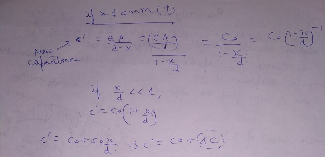
- The capacitance is increased .
- If object is not moving then capacitance is equal to Co.
- If object comes close to the fixed plate then capacitance increases.
- If object moves away from the fixed plate then capacitance decreases.

Inductive type proximity sensor
- Inductance :amount of magnetic flux linked to the coil per 1 ampere current ,if more amount of magnetic flux is linked per one ampere current then we can say that the inductance of coil is high.
- Reluctance :it is the opposition offered by medium to magnetic flux .

- If air gap increases reluctance faced by magnetic flux increases and total flux decreases therefore inductance decreases.

Photoelectric proximity sensor
- It used a beam of light to detect the presence of objects that block or reflect the light beam.
- A beam of light passes from the light source and a photo detector detects the presence or absence of light from source.
- Incandescent lamps or infrared led is may be used as light source.
- Photodiode, phototransistor are used as light detectors.


Types of stepper motor
- Variable reluctance type stepper motor
- Permanent magnet type stepper motor
- Hybrid stepper motor

- The rotor is having low mass.
- It is more responsive.
- The torque provided is low.

- It requires very low current this means it requires very low electrical power.
- It provides high torque compared to variable reluctance type stepper motor.

Application of stepper motor
- Stepper motor is used where resize positioning is required in combination with the microprocessor controller.
- It can accelerate its load easily on maximum torque occurs at low pulse rate.
- It is used in computer printers ,robotics, machine tools ,etc.
- They convert liquid air pressure into mechanical power.
- Hydraulic actuator use liquid pressure.
- Pneumatic actuator use air pressure.
- It is a device convert liquid press pressure into linear displacement or angular displacement.
- The output mechanical power depends on flow rate applied and pressure applied on piston .
- There are two types of hydraulic actuato:
- Linear actuator (hydraulic cylinder)
- Hydraulic motor (rotary actuator)
- Single acting type cylinder
- Double acting type cylinder
- Telescopic type cylinder
- Tandem type cylinder
- It can provide only one side stroke with the help of liquid pressure energy.
- Energy stored in the spring can be used to get return stroke.


- It provides two sides stroke with the help of liquid pressure energy .


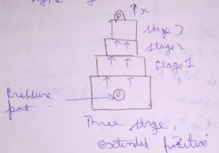
- Both extension and retraction will be done stage by stage.
- When we require large stroke length we use telescopic type cylinder.

- More than one cylinder connected in cascade configuration forms tandem type cylinder .
- It transmit heavy force without changing the dia of cylinder.


- They are the hydraulic or pneumatic equivalent of electric motors which are used when a twisting or turning motion is required.

Gear motor

Electrical actuator vs mechanical actuator
- They are portable and low power devices.
- These can be programmable hence they can be used in digital control applications.
- They provide very low output, hence cannot be used to drive heavy loads .
- Maintenance of these actuator is quite easy compared to mechanical actuator.
- These are little bit complicated to built.
- It is comparatively difficult to program.
- These provide very high mechanical output ,hence they can be used to drive heavy load also.
- Maintenance of these actuator is quite difficult.

0 Comments