Manufacturing process
- It is the process of converting row material into finished product .
- The process of value edition to the raw material ,such that final object will have more value in the market when compared to raw material .


- Casting
- Forming
- Fabrication process
- Material removal process
- Zero process
- Additive process
- Subtractive process
- Fused deposition modelling
- Selective laser sintering
- Laminated object manufacturing
- 3D printing
- It is a process in which molten liquid metal is allowed to solidify in a predefined mould cavity. After solidification by breaking the mould required shape of the object can be produced.


Advantages
- Complex shape of the objects can be easily produced.
- It is a less expensive process .
- Ductile and brittle materials can be easily produced.
- Large size objects can be easily produced by casting only.
- Example machine tool bad ,road roller, engine blocks ,etc.


- Casting objects are not having smooth surface finish.
- It is a laborious and time consuming process.
- Gas defects can be expected in the casting.
- Casting objects are not having uniform mechanical properties due to non-uniform cooling.
- Shape and size of the object.
- Properties required by the object.
- Accuracy and surface finish required by the object.
- Number of objects to be produced.
- Cost of the object.
- Shrinkage or contraction allowance
- Draft or taper allowance
- Machining or finish allowance
- Shake or rapping allowance
- Distortion or camber allowance

- When the liquid metal is allowed to solidify in the cavity there is a contraction or shrinkage of the material.
- When the liquid metal is cooled from pouring to freezing temperature shrinkage is liquid shrinkage.
- During phase transformation shrinkage of the material is solidification shrinkage .
- when the solid casting is cooled from freezing to ambient temperature shrinkage is solid shrinkage.
- Liquid and solidification shrinkage can be compensated by providing riser. These values are expressed in terms of percentage of shrinkage volume.
- Solid shrinkage can be compensated by providing shrinkage allowance on the pattern.
- Liquid and solidification shrinkage is maximum for aluminium which requires more volume of the riser.
- Solid shrinkage is maximum for lead and zinc .
- Total shrinkage is maximum for steel.

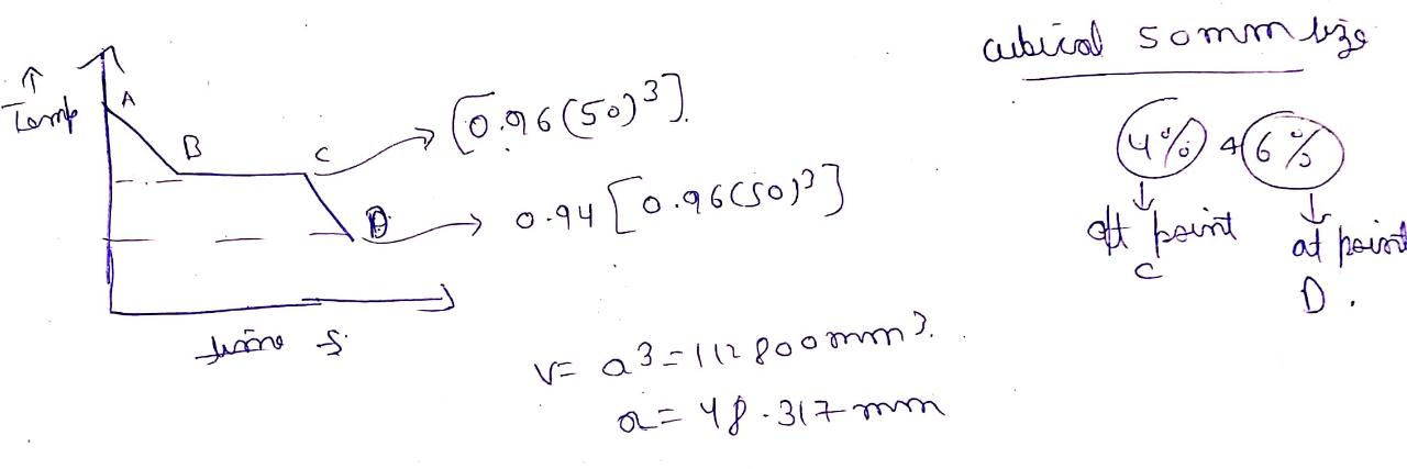
Question :a cubical casting of 50 mm size undergoes volumetric solidification shrinkage of 4% and volumetric solid contraction of 6%. There is no riser is used. What is the final size of the casting?
Grey cast iron
- In case of grey cast iron in liquid and solidification state there is the expansion of material this is due to conversion of carbon into graphite flakes. In solid state there is a contraction of the material to overcome this shrinkage allowance is provided on the pattern. There is no need of riser.


Draft allowance

- For the easy removal of the pattern to minimise continuous contact between pattern and mould surface for the vertical surface of the pattern draft of taper allowance is provided on the pattern.

- Casting objects are not having smooth surface finish, to get smooth surface finish machining is required. Due to machining, size of the casting will be reduced. To overcome this size of the pattern can be increased by providing machining allowance.

- For the easy removal of the pattern from the mould some clearance is required between pattern and mould surface. This can be produced by shaking the pattern due to shaking ,size of cavity will be increased. To overcome this size of the pattern can be reduced by providing shake allowance , it is a negative allowance provided on the pattern. For small size casting this can be negligible.

- Due to differences in shrinkage values there is distortion in casting. To overcome this distortion allowance is provided on the pattern opposite to the direction of distortion.

Pattern 


- It is the replica of final costing to be produced with some allowances.
Pattern materials
- Wood
- Metal and alloys example aluminium ,cast iron ,steel, brass, etc.
- Plastics -- polysterene , foam, PVC ,thermocol .
Single or solid piece pattern

- If the object to be produced is simple in shape and size, solid or single piece pattern can be used if one of the surface of the pattern is flat.

- If the complexity of the pattern is more it can be split into number of split pieces along the parting line and the split pieces can be removed from cope and drag boxes separately.

- If the patterns are having internal projections or undercuts loose piece pattern can be used. After removing of main part of the pattern loose pieces can be removed from the mould to get required cavity.

- To produce small size objects in mass production, producing of the gating elements manually will take more time ,to overcome this number of patterns along with getting elements will produce a single pattern known as gated pattern.

- To produce small size complex size of the objects in mass production number of patterns can be split along the parting line and they will be added on both sides of match plate along with gateing elements to produce a single pattern known as match plate pattern.

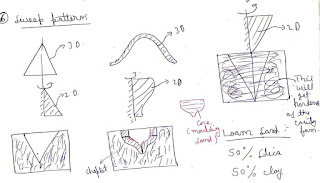
- To produce complex shape of 3D cavities, 2D planes patterns will be rotated in the mould. It is used to produce axis symmetric objects only like cone ,cylinder ,large size balls etc.

- If the pattern is not having sufficient strength, they are structurally weak due to ramming force there is a possibility of breaking of the pattern. To overcome this patterns are supported by providing follow board .

Core prints
- These are projection on the pattern ,they used to produce recess in the cavity to position the core properly.
- These are the metallic objects used to support the core inside the cavity.


Properties
- Refractoriness :it is the ability of moulding sand to withstand high temperature of the liquid metal without fusion.
- Permeability: ability of the moulding sand to allow the gases to escape is known as permeability. It is expressed by permeability number. Rate of flow of air passing through the given volume of specimen at a given pressure for a given time is called permeability number.


- Flowability :ability of the moulding sand to flow into on the corners of the mould box due to ramming force.

- Strength :to retain shape and size of the cavity and to withstand force applied by the liquid metal, mould must be having sufficient strength. If the molding sand is having moisture than it is called green sand. After evaporation of the moisture sand will become dry. After the sand will become dry, still liquid metal is having more heat will increase the temperature of the sand and it will become hard.
- Hardness: to minimise erosion and to withstand force applied by the liquid material on the mould surface, mould must be having sufficient hardness. It is expressed by mould hardness number. If hardness is more than 80 permeability will be reduced. If hardness is less than 60 dimensional changes can takes place in the casting.
- Adhesive property: bond formation between two different materials
- Cohesive property: bond formation between two similar materials.
- Moulding sand also requires efficient thermal conductivity and low coefficient of linear expansion.
- Collapsibility: ability of the molding sand due to which mould surface will not provide any resistance due to solid contraction of the casting. It can be improved by adding some additives to the molding sand.


- Saw dust or wood floor for collapsibility and permeability
- Linseed oil ,molasses , dextrin for strength of hardness
- Coal dust for surface finish

Objectives of getting design
- Design the gating element such that the liquid metal can be enter into the cavity with optimum velocity within a given time without causing turbulence splashing and molding erosion.
- Design the gating element so that pure metal can be enter into the cavity without air aspiration effect.
- Produce the grating element to get maximum casting yield.

- Pouring basin is designed to reduce the velocity of liquid metal which entered into the sprue to minimise erosion.
- Atmospheric gases can be absorbed into low pressure areas in the gating element is known as air aspiration effect. To overcome the air aspiration effect ideal shape of the sprue is parabola ,to overcome the manufacturing difficulty shape of the sprue is considered as a tapered cylinder.

- To maximize the discharge and to minimise the turbulent losses the shape of the runner will be considered as trapezoidal.
- But it is having more surface area to minimise heat transfer losses ,shape of the runner will be considered as cylindrical.
- It is actual entry point through which liquid metal can be enter into the cavity .

- Liquid metal is directly entering into the cavity from the bottom of sprue at atmospheric pressure.
- Velocity of liquid metal in the cavity is high.
- There is a chance of turbulence and splashing. It can be used for casting of ferrous materials.
- There is favourable temperature gradient of the liquid metal in the cavity.


- Gate is provided at the bottom of the cavity.
- Velocity of the liquid metal in the cavity it is negligible.
- There is no turbulence and splashing.
- It can be used for casting of non ferrous materials.
- There is unfavourable temperature gradient of the liquid metal in the cavity.
Parting line gate

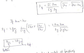
- Gate is provided along the parting line such that below the parting line cavity can be filled by assuming top gate and above the parting line cavity can be filled by assuming bottom gate.
- To get the advantage of both top and bottom gate it is most commonly used gating system.
Step gate

- To fill the molten liquid metal into very large moulds cavity number of gates are provided vertically in the form of step. Liquid metal can gradually fill into the cavity within a given time without causing turbulence and splashing.


0 Comments