Control valve
what is control valve?
Why we require control valve ?
- It changes amount of flow and direction of fluid flow.

- The graph drawn between percentage of flow rate and percentage of stem movement shows inherent characteristics of control valve.
- The flow characteristic depend upon shape of plug.

- Depend upon shape three types of control valve are there

- Linear valve
- Quick opening valve
- Equal percentage valve
- The output flow rate of fluid changes is directly proportional with step movement.


- The flow rate rapidly increase even for small change in stem movement. The sensitivity of quick opening valve is very high compared to other types of valve.


- The percentage change in output flow rate of the fluid is constant for the same increment of stem movement at any particular stem position.


- Single seated control valve
- Two seated control valve
|
Single
seated control valve |
Two
seated control valve |
|
Pressure drop at orifice decreases.
|
In the two orifice openings are available , as a
result upward force created by fluid at one orifice will be cancelled by
downward force created by fluid at other orifice , so we don’t require excess
pressure to push them . |
|
The advantage is it can be fully open and fully closed
, so as a result the output flow rate can be varied from 0% to 100%. |
Due to difference in temperature of stem and valve seat both , can’t
be reached simultaneously as a result if one plug is fully closed other plug
can’t close the orifice fully because of this. We can’t shut down the flow
rate completely. |
|
The disadvantage is we require to apply heavey
pressure at port to over come the upward force developed at orifice because
of pressure drop. |
|
|
This is reason why , these valve are used to
handle lower flow rate. |
|
Control valve part 2
- Based on actuation
- Based on construction
- Direction control valve
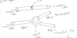
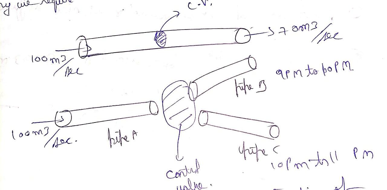
- Actuation mechanism is done by air pressure ,when the air pressure applied on diaphragm is increased then stem displaces from its initial position. This lead to change in orifice area which in turn changes fluid.
- The action is done by liquid pressure when the liquid pressure is applied through pilot port is increased then spool/ piston displaced from its initial position. This leads to change in orifice area which in turn changes fluid flow rate which is growing from port P to port A .


- Actuation is done by electrical current , when current is passing through a coil then magnetic flux will be developed because of which plunger moves in upward direction that leads to change in orifice area which in turn change the fluid flow rate.
- Gate type control valve
- Globe type control valve
- Pinch type control by
- Ball type control valve
- Butterfly type control valve
- Plug type control valve
- Check valve : fluid flow is allowed only in one direction and the flow will be blocked in other direction.


- 2 way and 2 position
- 2/2 directional control valve
- 4/2 directional control valve
Question : an actuator having a stem movement at full travel of 30 mm is mounted with the control valve having an equal percentage plug and with minimum flow rate of 2 metre cube per second and maximum flow rate is 24 metre cube per second. When the stem movement is 10mm the flow rate will be?

- It has an interconnection of many components which work together to deliver desired response as per engineer or operator requirement.
- Ideally the output of control system should be equal to set point as early as possible and as accurate as possible.


- If we fix the set point than the response or output should reach to the set point as early as possible and as accurate as possible.
- If there are fluctuations or disturbances in output and control system should eliminate effect of disturbance and make sure that output should be at desired setpoint.
- Process / plant/ system : every control system consists of this whose behaviour or responses to be brought to desired value.
- Controller: in recent time there is an electronic device and consists of predefined program and release output based on the requirement of operator and output of process. example microprocessor/ microcontroller is called as controller.
- Actuation system : it receives current from the controller and delivers mechanical output which in turn changes the process and plant output, example motor + fan together is called as actuation system.
- Sensor: it is a device measures the output or response of system and provides information to controller. example temperature sensor is used .
- This system does not consist of feedback. Hence controller is unable to get the information of output or response of the system.
- Block diagram


- This system consists of feedback and controller is able to get the information of output or response of a system with the help of sensor.
- Block diagram


Question : explain the following terms:
- Stability of system : it is the ability of system to come back to its initial steady state is called as stability Ideally the system should be stable.
- Steady state error: it is difference between setpoint and process variable after long time ,ideally the steady state error should be zero.
- Response time : the time taken for the process variable or output of system and response of the system to reach to the desired value.
- Servo mechanism : it is mechanism used in control system which helps the process variable to reach the required reference input or set point. if the servo mechanism is stronger than the output of control system reaches at point accurately with in short time.
- Regulatory mechanism: it is mechanism used in control system which helps to eliminate the effect of disturbance and making the whole system insensitive to the disturbance of reducing its effect on overall system performance.
- Ideally controller should make error equal to zero as early as possible.

- The change in current delivered by controller is directly proportional to change in error.
- Advantages :it is simple ,very simple to design and implement,For higher value of Kp the speed of response will be increased.
- Disadvantage : if we increase the gain we can reduce steady state error but we cannot eliminate it completely.

- The change in current delivered by controller is directly proportional to integration of change in error.
- Advantage: it can result in zero steady state error.

- Disadvantage : it works very slowly. It may generate oscillatory response.

- The change in current delivered by controller is directly proportional to derivative of change in error.
- Advantages : it can speed up the response. It provides dumping because of which system stablity can be improved.
- Disadvantage :for lower order system it may not result zero steady state error. If error is constant then the change in current generated by controller will be zero.


- It is also called as universal controller .

- It consists of advantages of proportional, integral ,derivative controller together.
- Advantage :it can increase the speed of response. It eliminates steady state error. It can improve stability of system.


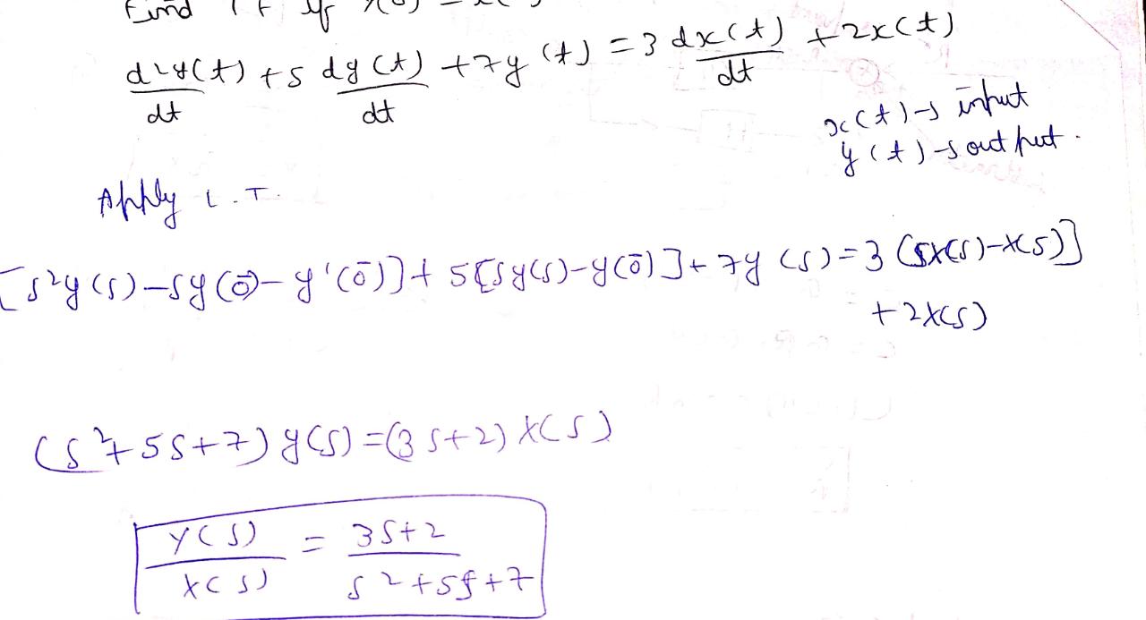
- The process of finding mathematical expression for a given system is called as mathematical modelling.
- It explains the relation between input and output of a component or system.


0 Comments