Coordinate measuring machine (CMM)
- A CMM is a device for measuring the physical geometrical characteristics of an object.
- This machine may be manually controlled or it may be computer controlled.
- Measurements are defined by a probe attached to the third moving axis of this machine.
- Probes may be mechanical , optical , laser or white light , amongst others.
- A machine which takes reading in six degrees of freedom and displays these readings in mathematical form is known as CMM.
Main components
- A CMM consist of four main elements:
- The main structure which include three axis of motion .
- Probing system
- Machine control and computer hardware
- Software for three dimensional geometry axis

Main structure
1. Cantilever

- A vertical probe moves in the z axis
- Carried by a cantilever arm that moves in the y axis
- This arm also moves laterally through the x axis
- Advantage - a fixed table allows good accessibility to the work piece
- Disadvantage - the bending caused by the cantilever design
- The cantilever design offers a long table with relatively small measuring ranges in the other two axis.
- Suitable for measuring long , thin parts
2. Bridge type
Advantage:
- Most widely used
- High rigidity owing to compact bridge design and thus small measuring deviations.
Disadvantage:
- Limited accessibility caused by the bridge.
Application:
- For medium to large measuring range
3. Column type

- Often reffered to as universal measuring machine instead of cmm
- This column type cmm construction provides exceptional rigidity and accuracy
- These machines are usually reserves for gauge room rather than inspection
4. Gantry
- The support of the workpiece is independent of the x and y axis , both are overhead , supported by four vertical column rising from the floor.
- This setup allows you to walk along the workpiece with the probe , which is helpful for extremely large pieces.
5. Horizontal
- Also referred to as layout machine .
- Has a moving arm and the probe is carried along the y axis
- Advantage - provides large area
- Ideal configuration of measurement of automobile parts.
Probing system
- It is the sensory part of the cmm responsible for sensing different parameters required for the measurements.
Stylus:
A pointed instrument used as an input device in the probe of a CMM
Types of probe:
- Transmission trigger probes
- Optical transmission probes
- Motorized probes
- Multiple or cluster probes
- Proximity or non contact probes
Inductive transmission probes

- They have been developed for automatic tool changing.
- Power is transmitted using inductive linking between modules fitted to the machine structure and attached to the probe.

- These probes also have been developed for automatic tool changing .
- It allows probe rotation between gaging moves , making it particularly useful for datuming the probe.
- The wide angle system allows greater axial movement of the probe and is suitable for the majority of installation.
Motorized probe
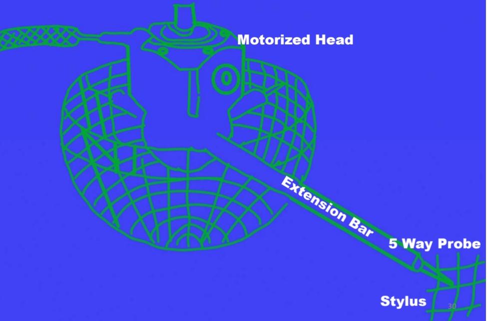
- With the motorized probe , 48 positions in the horizontal axis , 15 in the vertical axis can be programmed for a total of 720 distinct probe orientation .
- A range of light weight extension , the head can reach into deep holes and recesses.
- The head of the probe is sufficiently compact to be regarded as an extension of the machine quill.
- This enables the inspection of complex components that would otherwise be impossible or involve complex setups.
Multiple stylus probe heads

- Wide range of styli have been developed to suit many different gaging applictions.
- The selection of stylus is done based on the application for which the probe is to be used .
Proximity or non contact probes
- Uses laser , capacitive or video measurement technology.
Laser probe

- A cmm equipped with a laser probe can convert a part of physical model into a digitized file.
- Such a file can be compared with other files and can be manipulated by designers to improve quality.
- Manufacturers can verify that each finished part measures exactly as designed.
- Laser triangulation probes are used to scan the surface and after scanning it transmits a continuous flow of data .
- Line lasers are the fastest way to inspect non linear surface .
- It is widely used in reverse engineering.
Automatic stylus change system
Machine control and computer hardware
- The control unit allows manual measurement and self teach programming in addition to cnc operation .
- The control unit is microprocessor controlled .
- Usually a joystick is provided to activate the drive for manual measurement.
Software for three dimensional geometry analysis
- In a cmm , the computer and the software are an inseparable part.
- They together represent one system
- The efficiency and cost effectiveness of a cmm depend to a large extent on the software.
The features of CMM software
- Measurement of diameter , center distance , length , geometrical and form errors in prismatic components, etc.
- Online stastics for statistical information in a batch.
- Parameter programming to minimize cnc programming time of similar parts.
- Measurements of plane and spatial curves.
- Data communication
- Digital input and output commands for process integration
- Program for the measurement of spur , helical , bevel and hypoid gears.
- Interface to cad software
Working principle of CMM
- CMM is also a device used in manufacturing and assembly processes to test a part or assembly against the design intent .
- By precisely recording the x , y , z coordinates of the target point are generated which can then be analyzed via regression algorithms for the construction of features.
- These points are collected by using a probe that is positioned manually by an operator or automatically via direct computer control.
Modes of operation
1. Manual mode:
- CMM has a free floating probe .
- The operator moves the x,y,z axes to establish contact with the part feature to be measured .
- The differences in scale reading among the contact points are the measurements.
2. Manual computer assisted:
- Electronic digital displays are added to cmm for making zero setting, to select inch/mm , to print data in the standard format.
- These features save time , minimize calculations and reduced errors.
- A joystick is used to drive the machine axes.
- The operators manipulates the joystick to bring the probe into contact with the job.
3. Direct computer controlled:
- This is fully programmable
- The cmm uses 'taught' locations of cad data , to decide where the probe contact the job, and then collects measurement data.
- The fully automated cmm allows the operator to place the job in a fixture or on a table . run a stored program , collect the data points, and generate an output report/SQC record.
Advantages of CMM
- Flexibility
- Reduce setup time
- Single setup
- Accuracy
- Reduce operator influence
- Improve productivity
- Universatility and ease of operation
Application of CMM
- Aerospace engineering
- Automobile engineering
- Reverse engineering
- Medical engineering
CMM in computer aided manufacturing

DMIS
- Dimensional measurement interface specification is a new standard in communication being used in CAM.
- It provides a bi-directional communication of inspection data between CAD system and inspection equipment so as to see what has to be made.


)
0 Comments