Concept of stress and strain
- The mechanical behaviour of a material reflects the relationship between its response or deformation to an applied load or force.
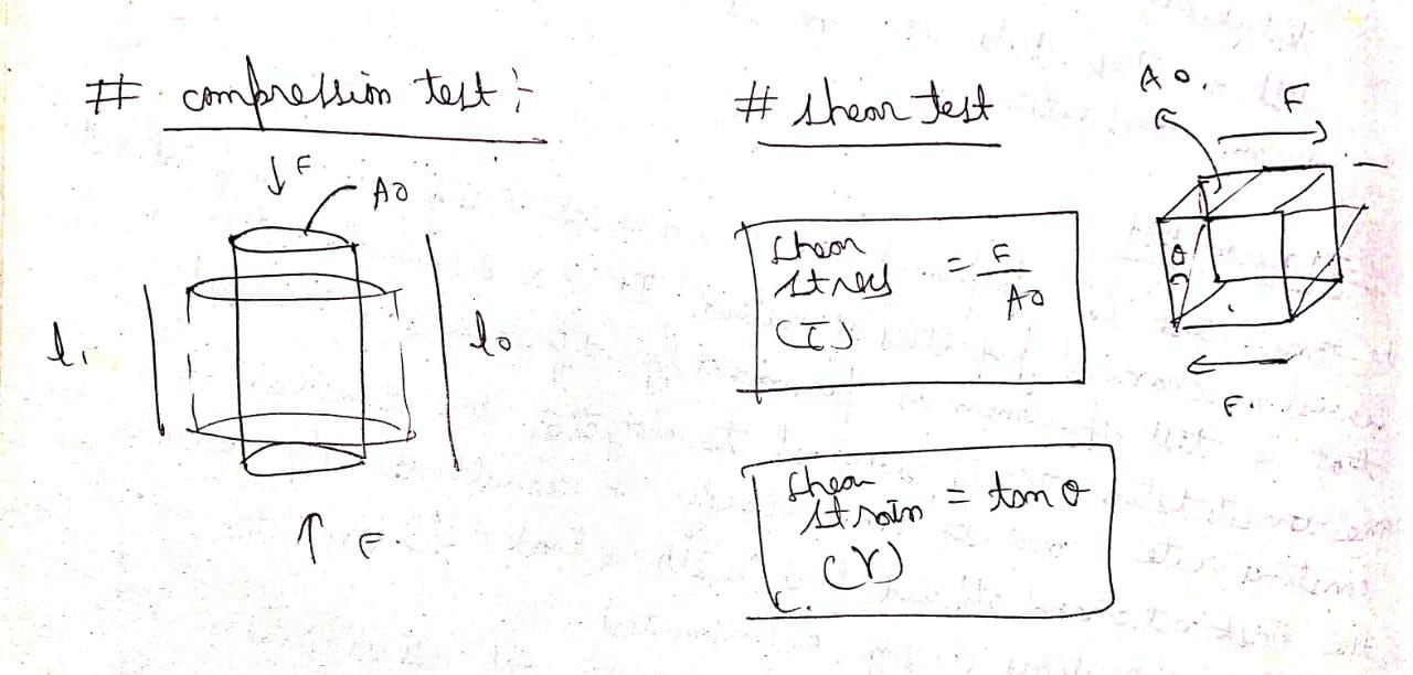
- There are three principal ways in which a load may be applied :tension ,compression and shear.
- If load is static or changes relatively slowly with the time and is applied uniformly over a cross section the mechanical behaviour may be as certain by a simple stress strain test. These tests are most commonly conducted for metals at room temperature.
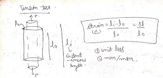
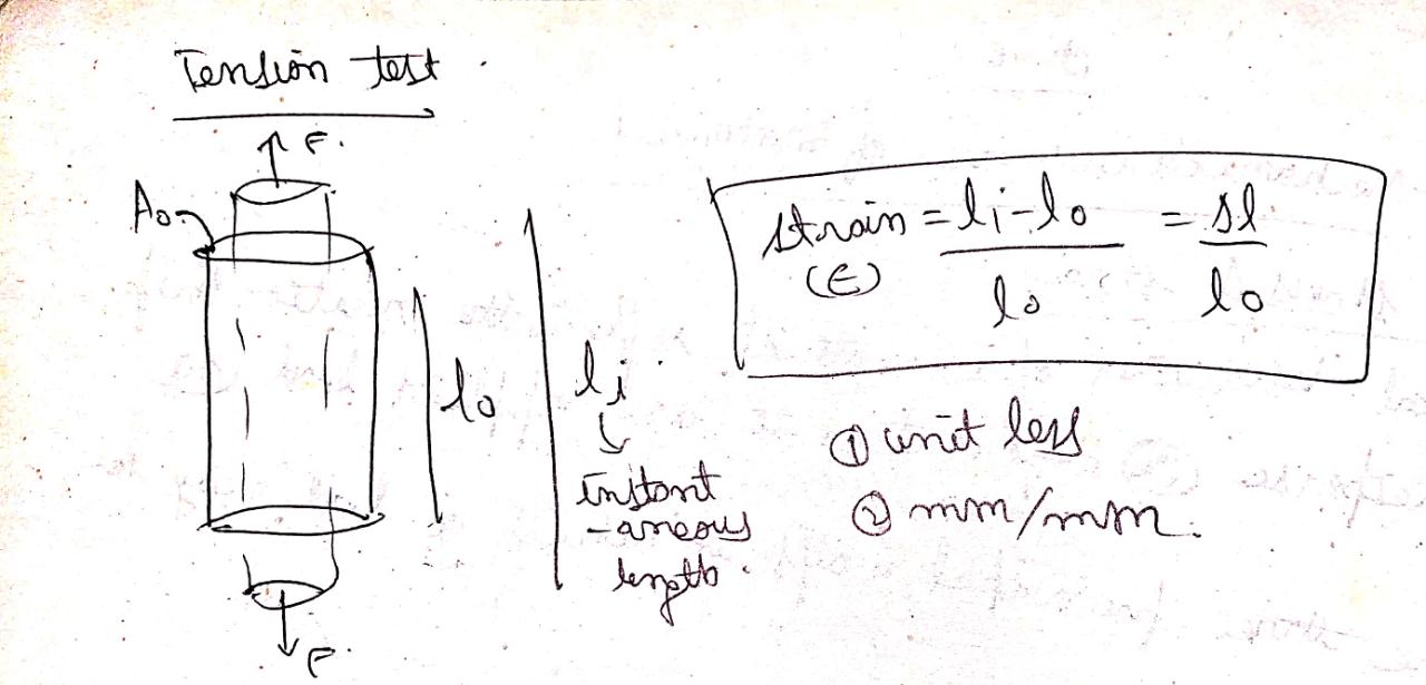
- The tension test is performed on a universal testing machine to find out several mechanical properties of materials.
- It is a destructive test that is test specimen is permanently deformed and fractured.
- The tensile testing machine is designed to eliminate the specimen at a constant rate and to continuously and simultaneously measure the instantaneous applied load with a load cell and the resulting elongation using extensometer.
- The load deformation characteristics are dependent on the specimen size. for example it will require twice the load to produce same elongation if the cross section area of the specimen is doubled.

- To minimise these geometrical factors load and engineering elongations are normalised to the respective parameters engineering stress and engineering strain.

Compression test
- for most metals that are stressed in tension and relatively low stress level ,the stress and strain curve are proportional to each other.
- Deformation in which stress and strain are proportional is called elastic deformation and a plot of stress vs strain results in a linear relationship the slope of this linear segment correspond to the modulus of elasticity this modulus may be thought of as stiffness or material resistance to elastic deformation.


- The greater the modulus the stiffer the material or the smaller elastic strain that results from the application of a given stress.
- Elastic deformation is non permanent which means that when the load is released then the metal piece returns to its original shape and size.
- Values of modulus of elasticity for ceramic materials are about the same as for metals. But for polymers these values are lower. These differences are direct consequence of the different types of bonding in three material types.
- With increase in temperature the value of modulus of elasticity decreases.


Anelasticity
- When a load is applied on a material at time To the elastic deformation will slowly continue for sometime before it reaches a steady strain value. When load is removed at time T1 it again take some time to recover back its original form such materials are said to be anelastic and such phenomenon is called anelasticity.
- Such material may or may not obey hook slow.
- When the deformation is time dependent and recovery is also time-dependent but the original shape and size is not fully recovered then such materials are known as viscoelastic and the phenomenon is known as viscoelasticity.


Plastic deformation
- Plasticity is defined as the ability of material to retain the deformation produced under the load on a permanent basis.

- Plastic deformation is very large and it is nonlinear in plastic region.
- During plastic deformation atoms of the metal are permanently displaced from their original position and take up the new position.
- From an atomic perspective plastic deformation corresponds to breaking of bond with original atom neighbours and then reforming bond with new neighbours as large number of atoms or molecules move relative to each other, upon removal of stress they do not return to their original position.
- When the specimen is stretched beyond E the strain increases at a faster rate that is without appreciable increase in stress , we also observed that material is permanently deformed or plastically deformed beyond the point E that is material starts yielding.


- As per offset method a convention has been established where in a straight line is constructed parallel to the elastic portion of the stress strain curve at some specified strain offset usually 0.002.
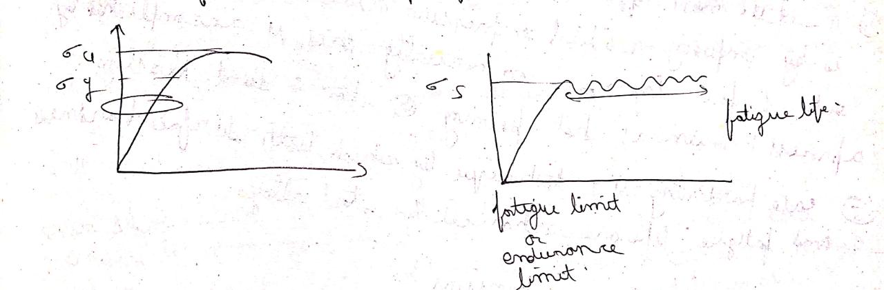
- The stress corresponding to the intersection of the line and stress strain curve in the plastic region is defined as yield strength.
- It is the maximum stress that can be reached in the tension test.
- The stress corresponding to the point M is called ultimate strength.
- Beyond maximum load at point M their is localised reduction in cross-sectional area called necking.
- As the test progresses the cross-sectional area reduces further and fracture takes place at the narrowest cross section of the neck (at point F).
- The stress corresponding to point F is called breaking strength or fracture strength.
- It is a measure of degree of plastic deformation that has been sustained at fracture.
- It shows the ability of a material to be with drawn into wires by applying tensile stress without losing much strength and without failure.
- It may be expressed quantitatively as percent elongation.


- It is that property of metal due to which a piece of metal can be converted into thin sheets by applying compressive stress.
- Malleable material process a high degree of plasticity.
Brittleness

- It is lack of ductility that is material cannot be stressed. In brittle material fracture takes place immediately after elastic limit with the relatively smaller deformation .
- For the brittle material fracture and ultimate stress point are same and after proportional limit very small strain is observed.
- It is defined as the ability of the material to sustain load without failure.
- Tensile strength: it is the ability of material to resist external load causing tensile stress without fracture.
- Compressive strength: it is the ability to resist external load that cause compressive stress without failure.
Resilience

- It is the capacity of material to absorb energy when it is deformed elastically and then upon unloading to have this energy recovered.
- The associated property is the modulus of resilience which is the strain energy per unit volume required to stress a material from an unloaded state up to the point of yielding.
- This resilient material are those having high yield strength and low modulus of elasticity such materials could be used in Spring applications.


- It is a measure of ability of a material to absorb energy up to fracture.
- It indicates the shock absorbing ability of a material for a sudden or impact loading.
- The toughness may be calculated from the stress strain curve and it is equal to the area under the stress strain curve up to the point of fracture.
- For a material to be tough it must display both strength and ductility often ductile materials are tougher than brittle materials.


- It is a destructive type of test.
- Impact test conditions are selected to represent most severe relative to the potential for fracture namely
- deformation at relatively low temperature
- A high strain rate
- A triaxial stress state which may be introduced by the presence of a notch.
- This test is performed by high velocity loading and introduction of a notch in a specimen to create notch sensitivity, (stress concentration) so that even the ductile material undergo a brittle type fracture.
- Impact strength can be measured by two standard test method :izod test or charpy test


- Hardness is a measure of material resistance to localised plastic deformation such as a small dent or scratch.
- Quantitative hardness techniques have been developed over the years in which a small indenter is forced into the surface of material to be tested under controlled conditions of load and rate of application.
- The depth or size of resulting indentation is measured which in turn is related to a hardness number.
- The softer the material the larger and deeper is the indentation and lower the hardness number.
- Hardness test are performed more frequently than any other mechanical test for several reasons. They are simple and inexpensive.
- The test is non destructive.
- Other mechanical properties may be estimated from hardness data such as tensile strength.
- Industrially used hardness test are :brinell hardness test(steel indentor), knoop or vicker's hardness test (diamond), Rockwell hardness test (diamond and steel both).


- It is the separation of a body into two or more pieces in response to an imposed stress that is static and that the temperature that are low relative to the melting temperature of the material.

- It is defined as the time-dependent and permanent deformation (progressive deformation of material over a period of time) of materials when subjected a constant load or stress.
- Creep is normally an undesirable phenomenon and often it is the limiting factor in the lifetime of a material.
- Creep is observed in almost all materials type.
- For metals it become important at temperature greater than melting point temperature.
- Amorphous polymers which include plastic and rubbers are specially very sensitive to creep deformation.
- Factors affecting creep are as follows:
- Type of loading
- Magnitude of load.
- Time for age of loading.
- Temperature.
- It is a form of failure that occurs in a structure subjected to dynamic and fluctuating stresses.
- Under these circumstances it is possible for failure to occur at a stress level considerable lower than the tensile or yield strength for a static load.
- Fatigue failure is brittle like in nature in normally ductile metals .
- there is a limiting stress level called the fatigue limit or endurance limit below which fatigue failure will not occur.
- This fatigue limit represent the largest value of fluctuating stress that will not cause failure.
- Another important parameter that characterises a material fatigue behaviour is fatigue life.
- It is the number of cycles to cause failure at a specified stress level.

- Corrosion : the corrosion of a material reduces the fatigue life or number of cycles at any stress to rupture of the material.
- Temperature : higher temperature encourages oxidation and corrosion on the metal surface thereby reducing fatigue properties.
- Surface defects: during machining operation small scratches ,dents ,tool marks etc may be introduced on the metal surface which may act as stress raiser or stress concentrator and thereby these surface markings can limit fatigue performance.
- Design factors :any notch or geometrical discontinuities such as keyways , sudden changes in cross section etc can act as stress reasons and fatigue crack initiation point.
- Structural irregularities such as keyways , sharp corners , etc should be avoided by proper design.
- Fine surface finish without surface irregularities and cracks is to be ensured by carrying out polishing.
- Materials with fine grain should be preferred.
- One of the most effective method of increasing fatigue performances by imposing residue and compressive stress within a thin outer surface layer ,commercially this is accomplished by a process known as shot peening or shot and sand blasting.
- Case hardening is a technique by which both surface hardness and fatigue life are enhanced for steel alloys .
- Alloying : alloying elements create an obstacle in the movement of dislocation and hence the strength of the material increases so alloys will always be stronger than a pure metal.
- Grain refinement : fine grain size led to higher number of grain boundaries and hence higher obstruction to dislocation leading to increase in strength.
- Strain hardening : it is a phenomenon whereby a ductile metal becomes harder and stronger as it is plastically deformed.
- Recrystallization temperature : it is defined as the temperature at which 50% of the material re crystallizes in 1 hour. Typically it is between one third and half of the melting temperature of a metal or alloy and depends on several factors including the amount of prior cold work and the purity of the metal or alloy.
- When deformation is achieved at temperature above the recrystallization temperature than the process is known as hot working process.
- For hot working operations large deformations are possible because the metal remain soft and ductile also deformation energy requirements are less than for cold working however most metal experience some surface oxidation which result in material loss and poor surface finish.
Cold working process
- When deformation is achieved at a temperature less than the recrystallisation temperature than the process is known as cold working process , cold working produces an increase in strength with decrease in ductility, since metal remains hard , advantages over hot working include a higher quality surface finish,
Rate of cooling : rate of cooling wether slow or fast decides the crystal structure.
- Annealing: very slow rate of cooling --- 10 degree celcius or less per hour
- Normalising : rate of cooling is moderate --- of the range of 50 degree celcius or less per hour
- Quenching : rate of cooling is greater than the critical cooling rate , critical rate is 350 degree celcius or more per hour
Precipitaion hardening or age hardening
- Aluminium copper alloy with less than 5.5% cu is heated to a temperature at which uniform distribution takes place in the microstructure , from this temperature material is quenched to room temperature as a result of that copper gets locked in the structure of aluminium , as the time passes copper starts coming out of the microstructure and forms precipitates of Al2CU.
- These precipitates crate an obstacle in movement of dislocation and this increases the strength of the material , this phenomenon is called precipitaion or age hardening .
- eg of alloys that are hardened by precipitaion treatment include aluminium - copper , copper - beryllium , copper - tin and magnesium - aluminium.


0 Comments